ORION
Peter Müller, March 19, 2022
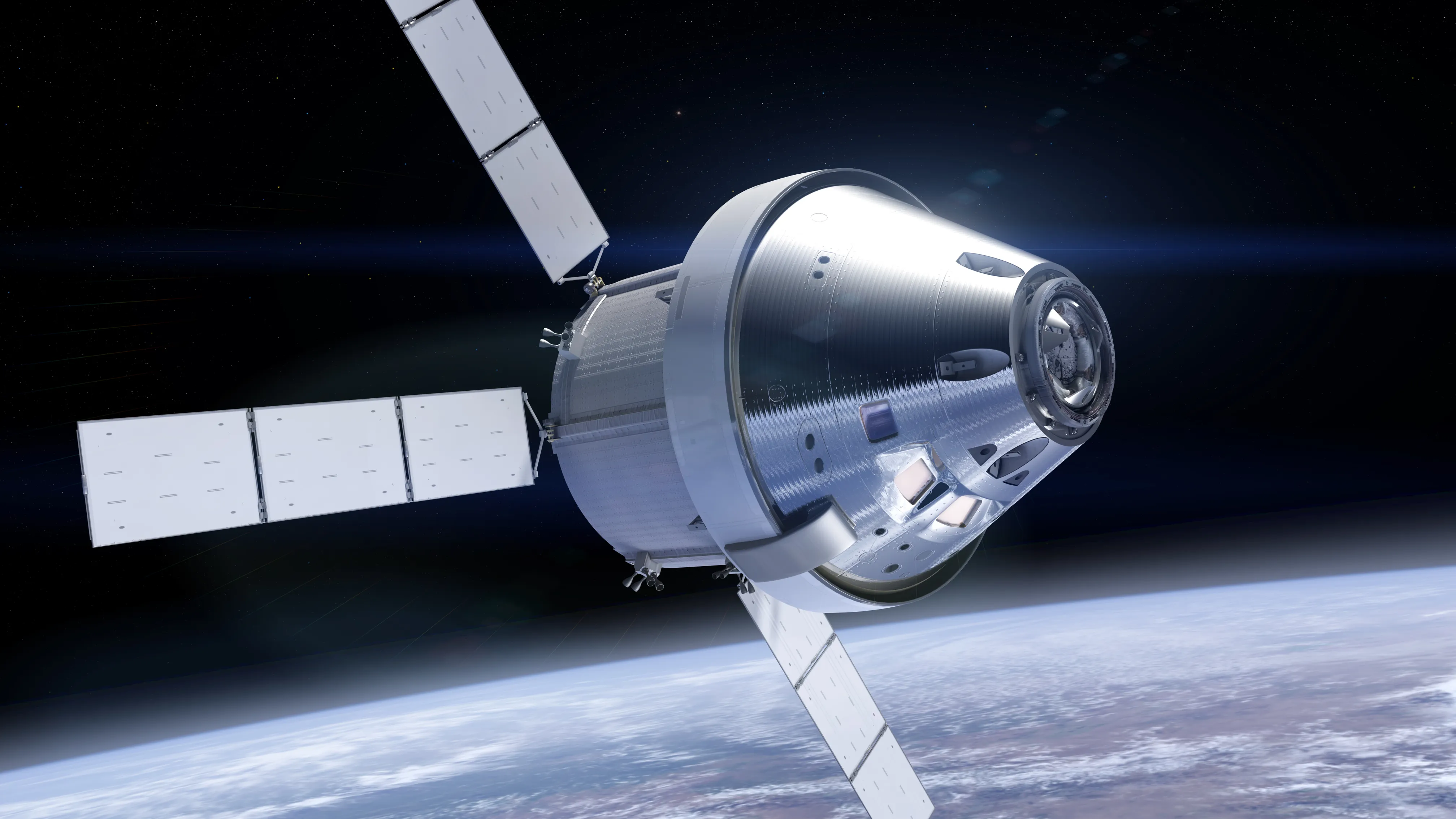
Earlier this month, Artemis 1 rolled out of NASA's rocket assembly bay and slowly moved towards the launch pad. The Artemis mission will launch an uncrewed Orion spacecraft and 13 tiny cube satellites to the moon. Once there, Orion will orbit the moon for up to 23 days until returning to earth and splash down into the ocean.
Twitter: Artemis-1 rollout by @NASA_SLS
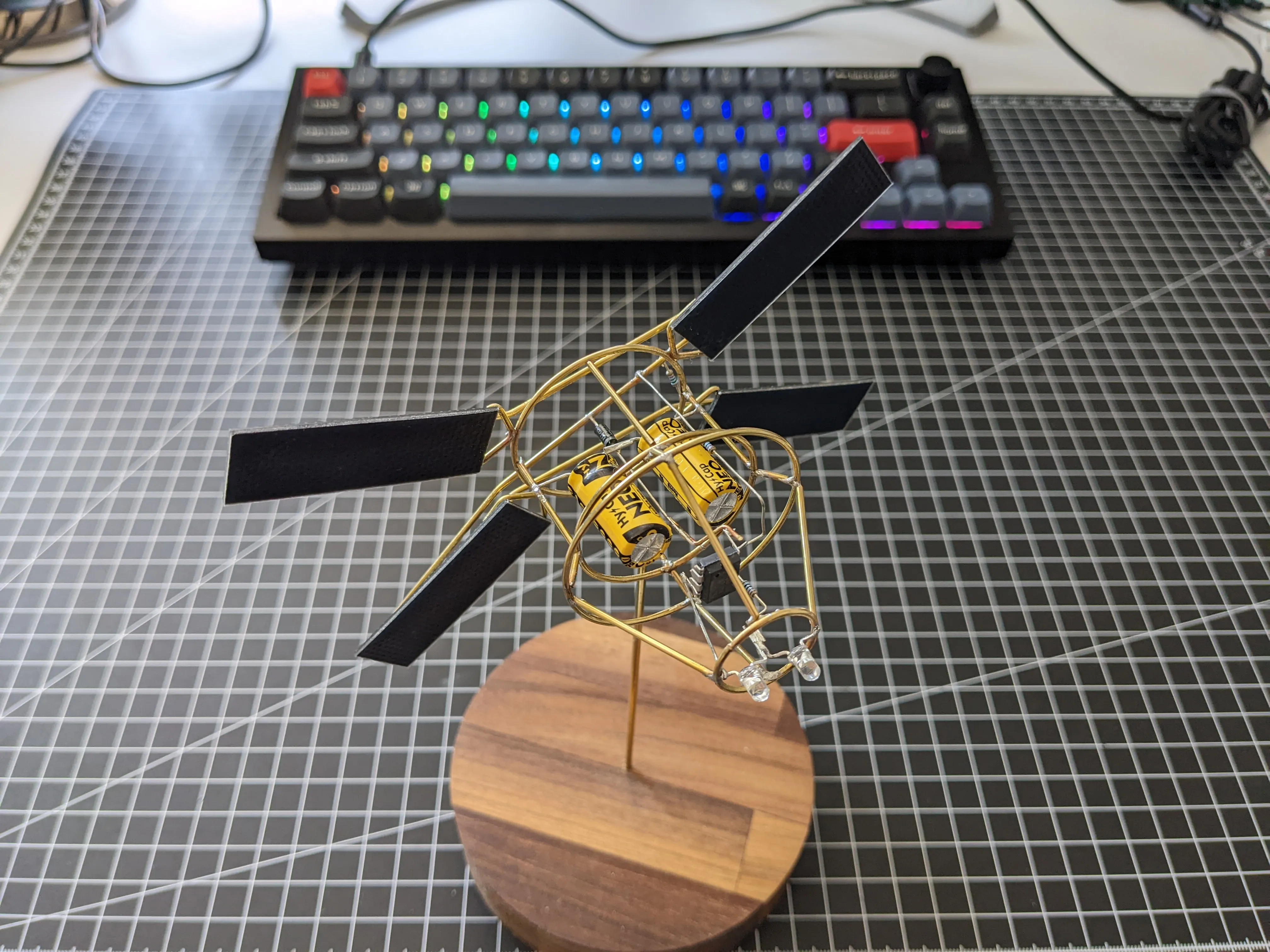
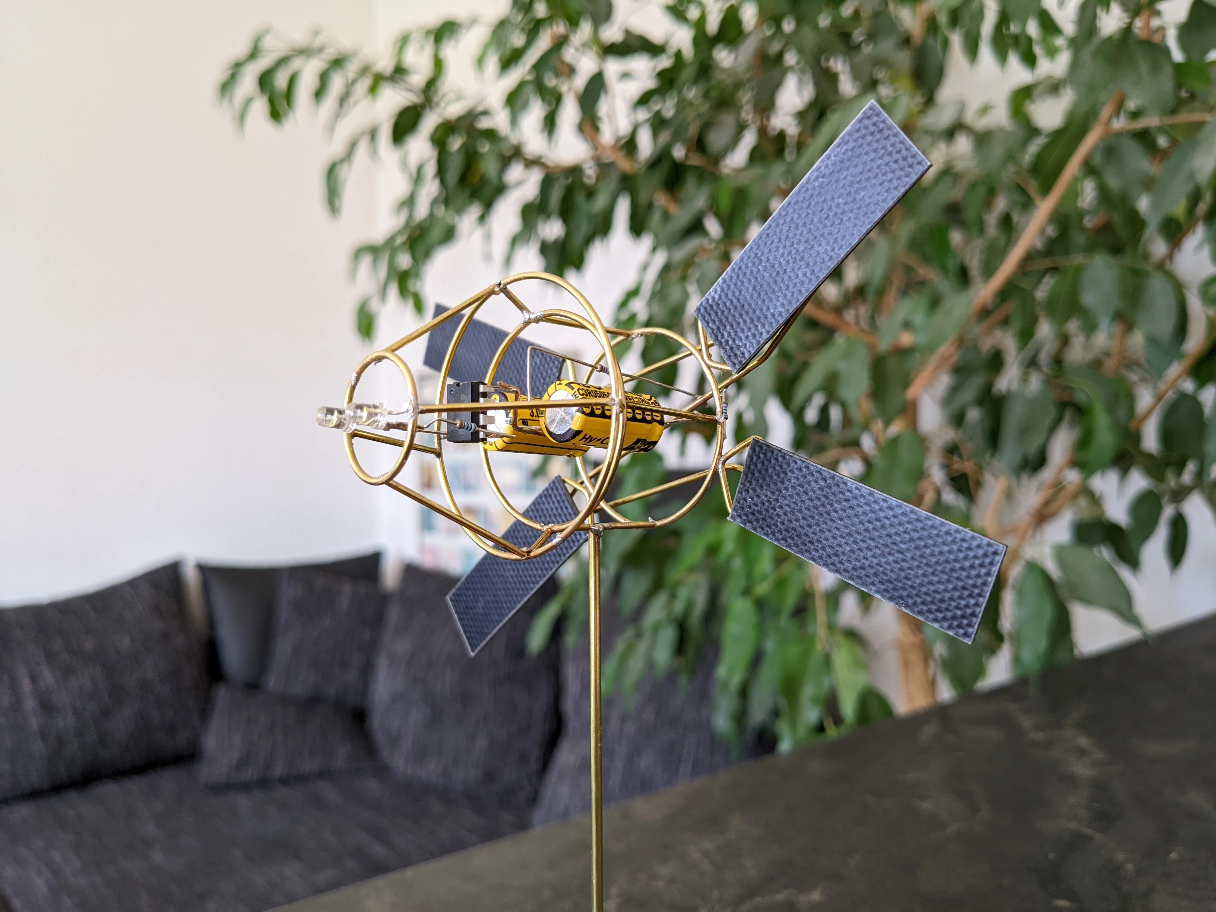
This mission excited me so much that I decided to build a smol Orion model. The spacecraft with its four solar panels looks really cool, and after my relatively simple cube sat from last time, I wanted to build a more complex model. Like SMOLSAT-1, this model is just be a solar-powered blinking LED. I was not very satisfied with the performance of my last model; the LED consumed the energy too fast and the behavior of the microcontroller was absolutely not smart.
With the ORION, the microcontroller now measures whether the solar cells are receiving sunlight and switches itself to power-saving mode to conserve energy. This way the model charges much faster. As soon as it is dark, the microcontroller switches on and starts the light show.
Parts
- ATtiny45 or 85 in PDIP format
- 2x 3V 5F supercapacitors
- 1× Schottky diode
- Resistors: 2× 10kΩ, 1× 150Ω
- 4× SM141K04TFV solar cells
- 1× LED
- 1.2 mm brass wire
- 0.8 mm brass wire
- Wooden base
For beginners I recommend this tutorial for Programming an ATtiny85 with Arduino Uno.
Software
Our goal is to minimize the power consumption of the microchip while charging the solar cells. To do this, we set the sleep mode to SLEEP_MODE_PWR_DOWN, which consumes the least power of all sleep modes. We also disable the analog to digital converter (ADC), since we don't use it and it would only consume extra power.
The pinout of the ATtiny45 looks like this:
            -|‾‾∪‾‾|-  Voltage (+)
            -|     |-  2 PIN_SOLAR_CELL
            -| •‿• |-
(-) Ground  -|_____|-  0 PIN_LED
On Atmel chips, each pin not only has a pin number, but also a special interrupt number that allows you to assign an interrupt to a pin. If a low voltage is detected at this pin, an interrupt is triggered, which brings the device out of sleep mode. For pin 2 the interrupt number is 0.
#include <avr/sleep.h>
#include <avr/wdt.h>

const int PIN_SOLAR_CELL = 2;
const int PIN_LED = 0;
const int INTERRUPT_NR_SOLAR_CELLS = 0;

void setup() {
  pinMode(PIN_LED, OUTPUT);
  pinMode(PIN_SOLAR_CELL, INPUT);
  set_sleep_mode(SLEEP_MODE_PWR_DOWN);
  disableADC();
}

// ADC is not needed and preserves energy if disabled
void disableADC() {
  ADCSRA = 0;
}
The program's main loop checks if the solar cells receive sunlight (have a high voltage) and thus charge the system. If so, the chip goes to sleep but attaches an interrupt to pin 2 before doing so. The interrupt wakes up the microchip up as soon as the solar cells stop receiving sunlight and the voltage on pin 2 drops low.
void loop() {
  if (solarCellHasSunlight()) {
    goToSleep();
  } else {
    flashLED();
  }
}

boolean solarCellHasSunlight() {
  if (digitalRead(PIN_SOLAR_CELL) == HIGH) {
    return true;
  } else {
    return false;
  }
}

void goToSleep() {
  attachInterrupt(INTERRUPT_NR_SOLAR_CELLS, handleInterrupt, LOW);
  sleep_mode();
}

// Immediately detaches the interrupt to avoid endless interrupt cycles
void handleInterrupt() {
  detachInterrupt(INTERRUPT_NR_SOLAR_CELLS);
}

void flashLED() {
  digitalWrite(PIN_LED, HIGH);
  sleep(WDTO_60MS);
  digitalWrite(PIN_LED, LOW);
  sleep(WDTO_60MS);
  digitalWrite(PIN_LED, HIGH);
  sleep(WDTO_60MS);
  digitalWrite(PIN_LED, LOW);
  sleep(WDTO_8S);
}
As a small tweak to further save power, we replace Arduino's delay() function, which only counts CPU cycles, with a proper sleep mode that shuts down the device and wakes it up after a timer is triggered.
The timer is the chip's watchdog clock, which interrupts the CPU once the countdown is over.
// Uses sleep mode instead of a delay to preserve energy
void sleep(int time)
{
  wdt_enable(time);
  enableInterruptMode();
  sleep_mode();
}

// Makes watchdog fire an interrupt instead of resetting the device
void enableInterruptMode() {
  WDTCR |= _BV(WDIE);
}

// Watchdog interrupt handler. Needs to deactivate watchdog in the first 15 ms
ISR(WDT_vect)
{
  clearInterruptFlags();
  wdt_disable();
}

void clearInterruptFlags() {
  MCUSR = 0;
}
And that's it! Check out the full code here: orion.ino
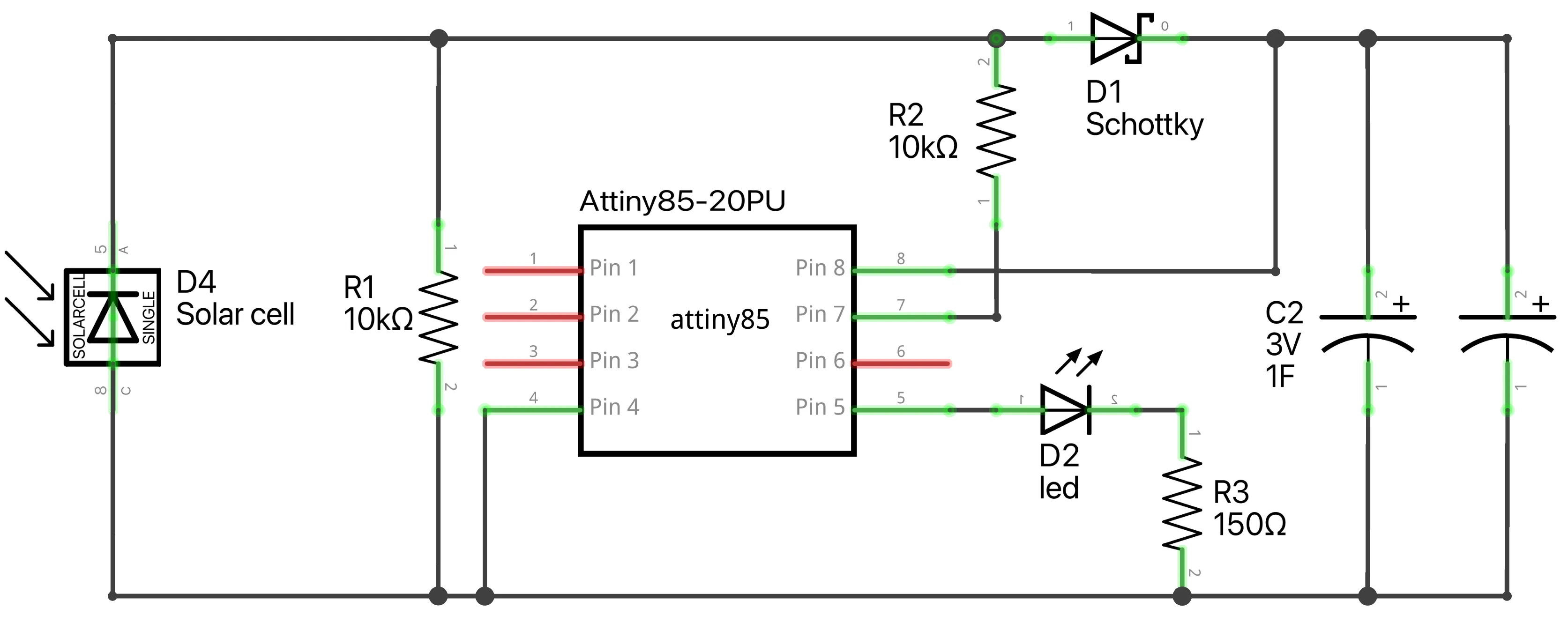
To make sure everything works properly, you should wire everything up on a breadboard and try it out before you start on the hardware. Here is the schematic and how it looks on a breadboard:
Hardware
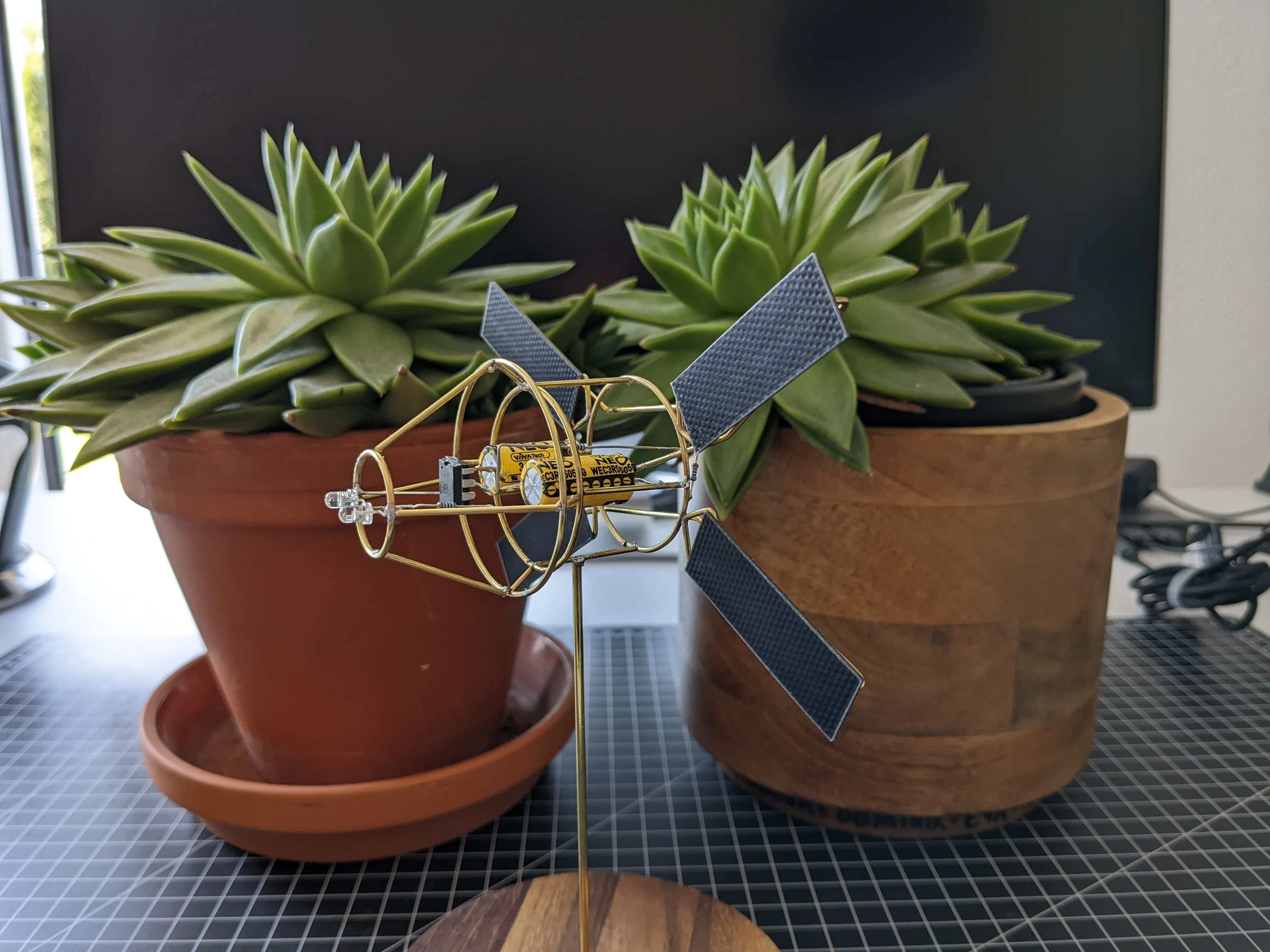
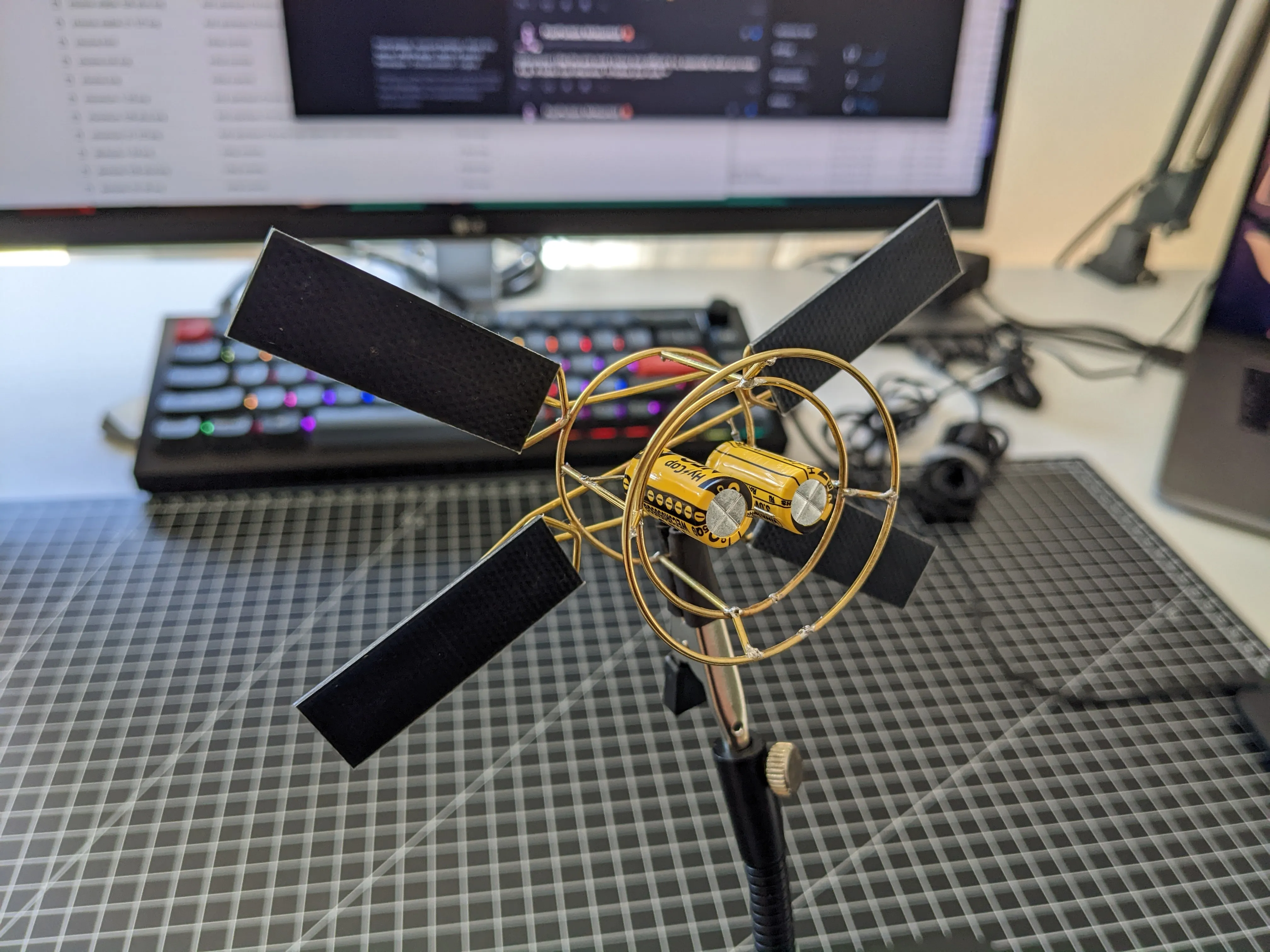
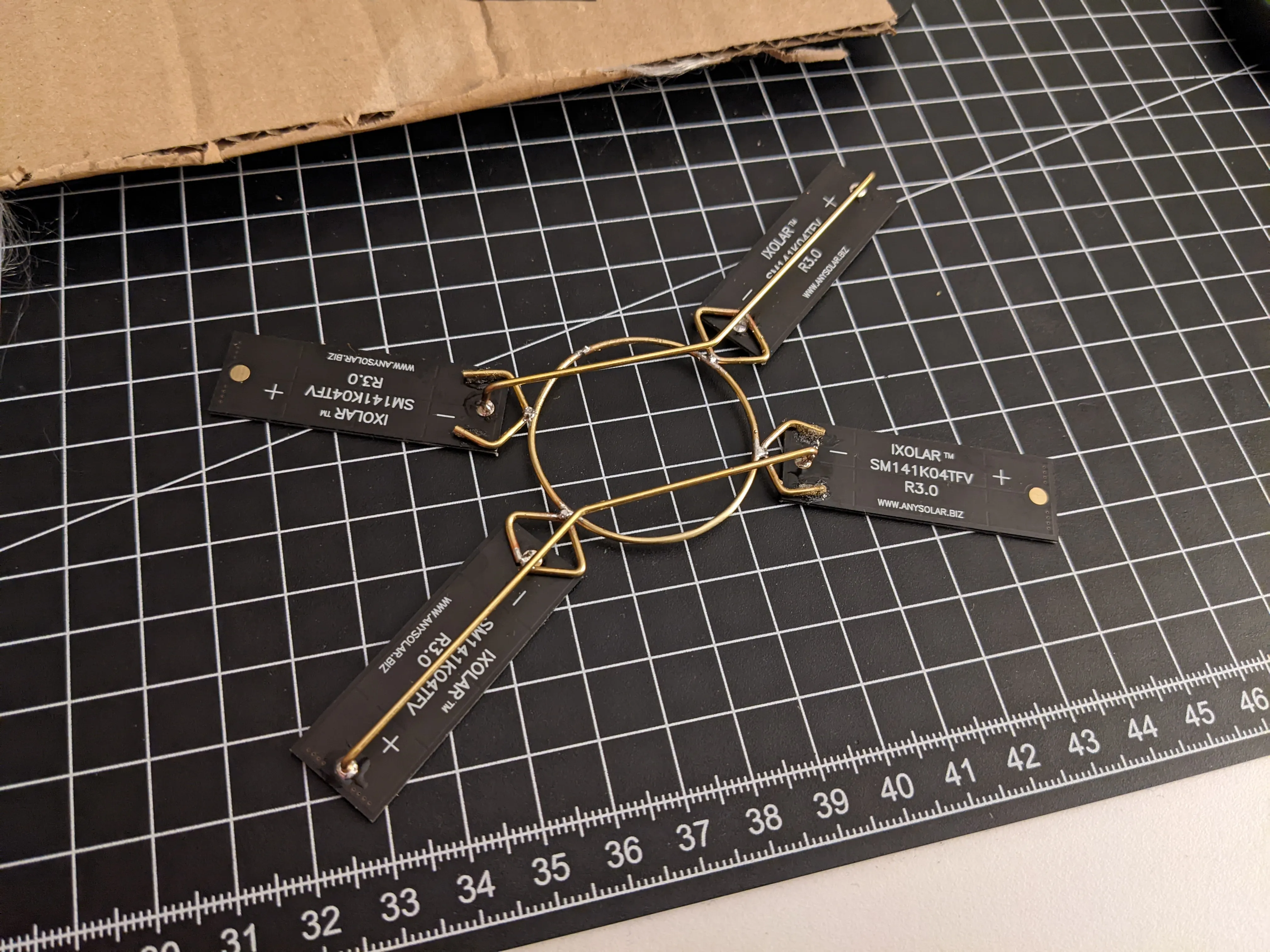
Building the model is the hardest part: lots of wires need to be formed into perfect circles and the overall structure is really difficult to solder together. I started with the back part, the solar cells, and worked my way to the front part.Since I started with the solar cells, I could test the circuit at any time during the build, as it was already generating power.

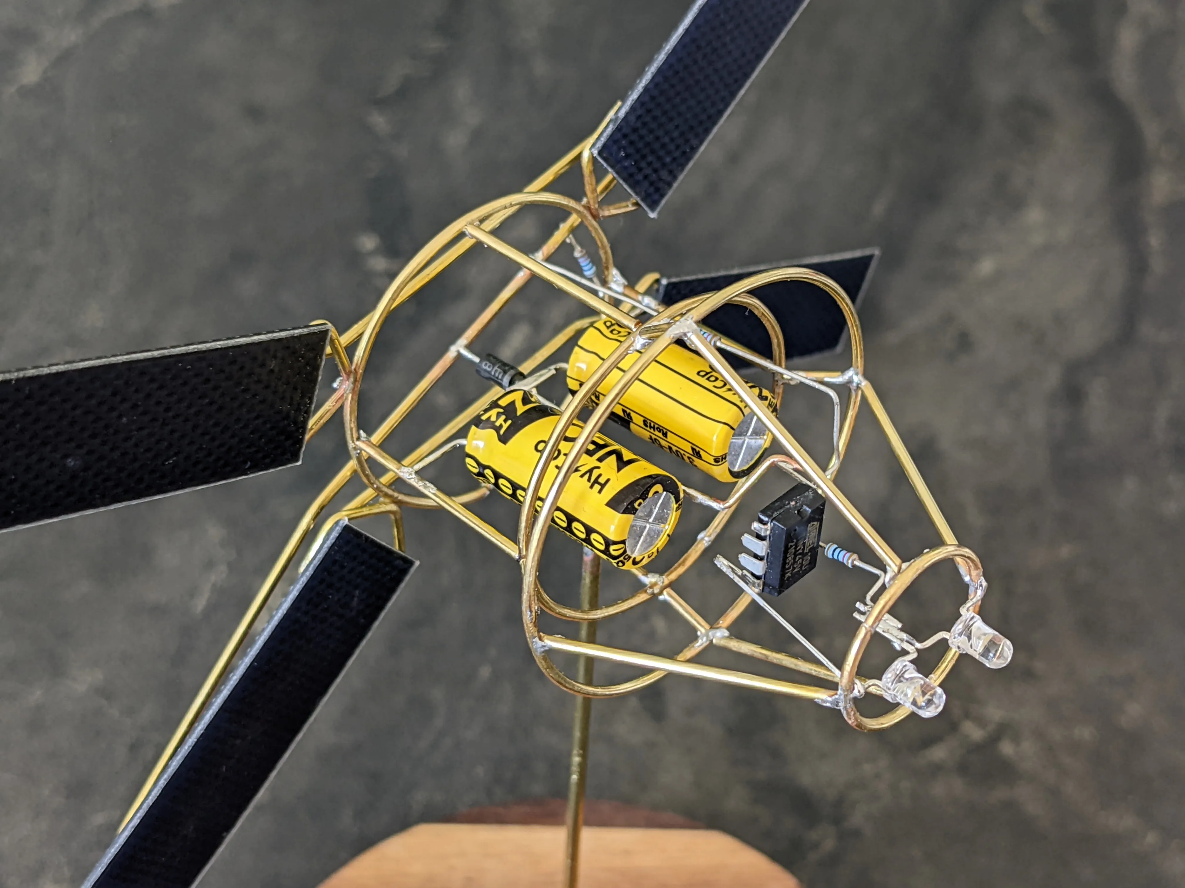
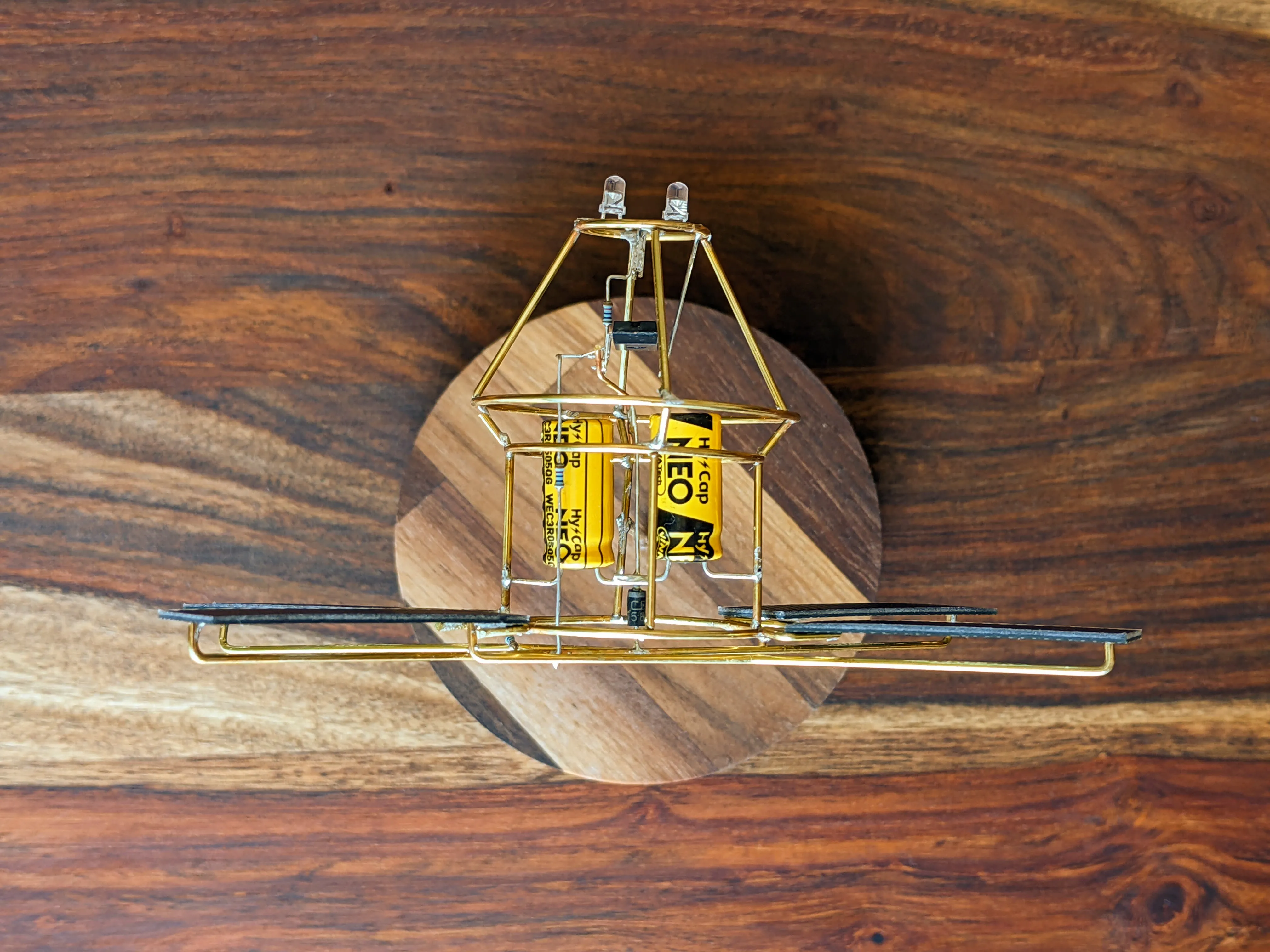
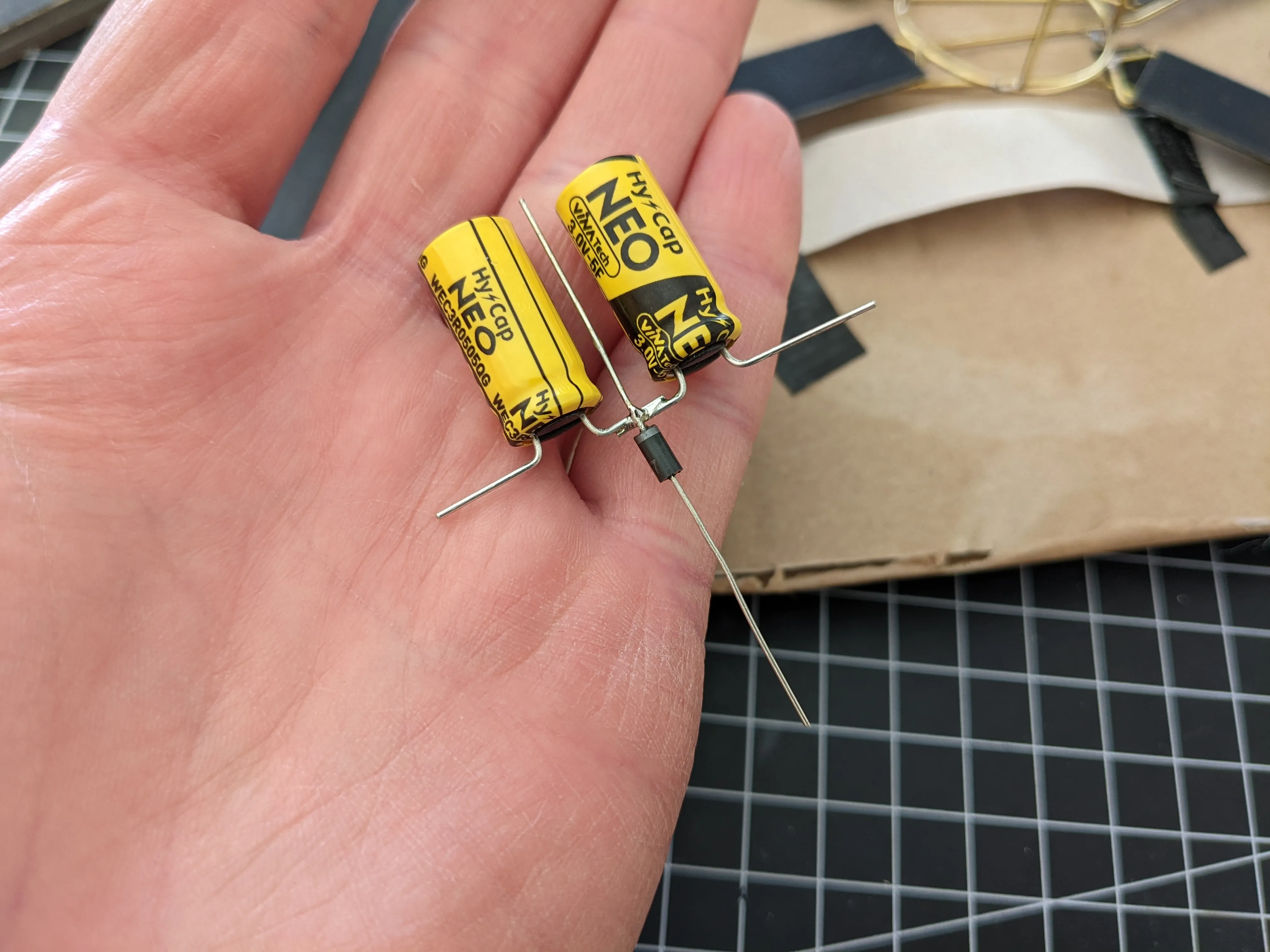
After the back plate was finished, I proceeded with the capacitors and diode. I decided to connect them first in a separate sub-assembly to make it easier to work with these components.
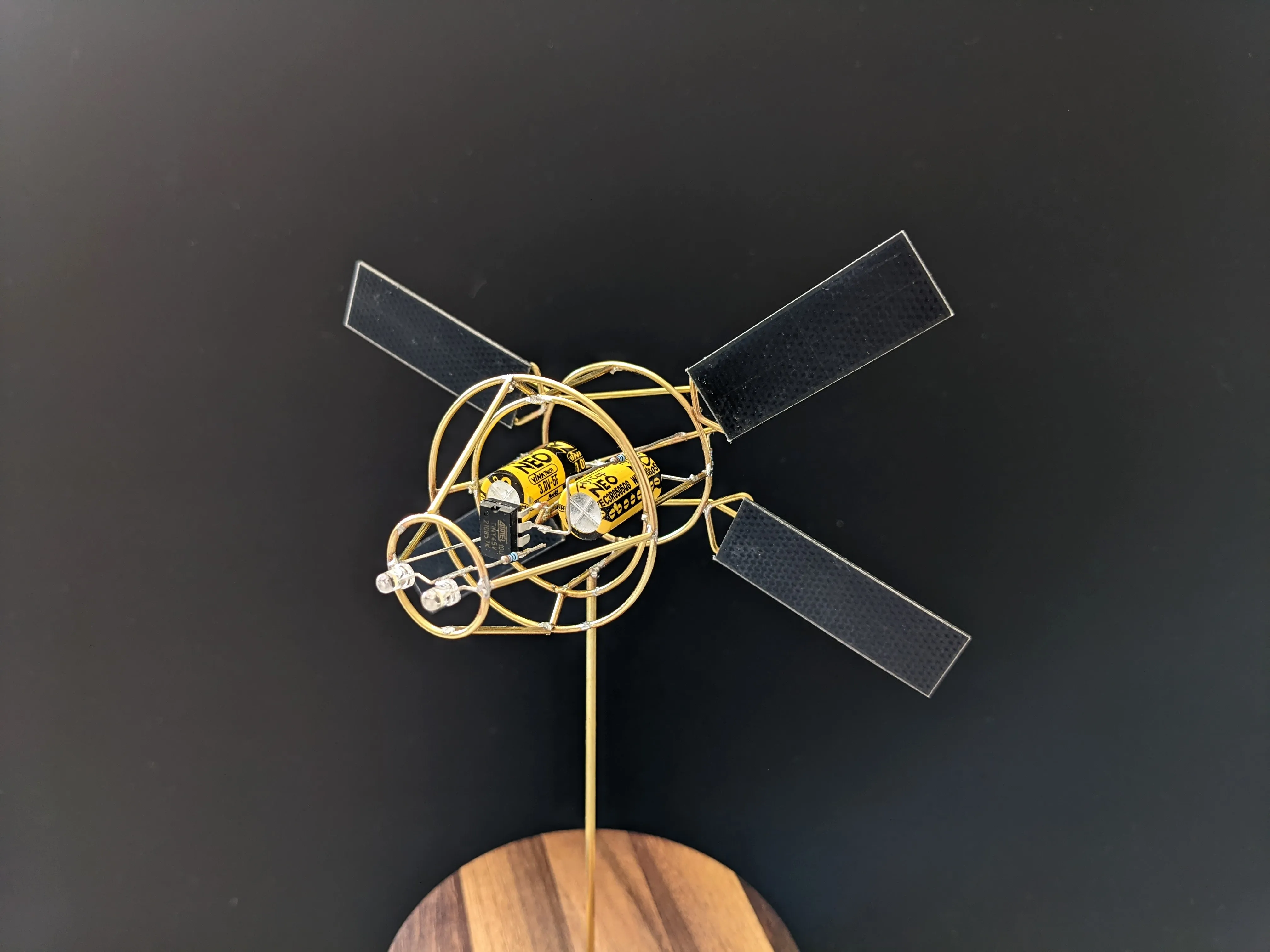
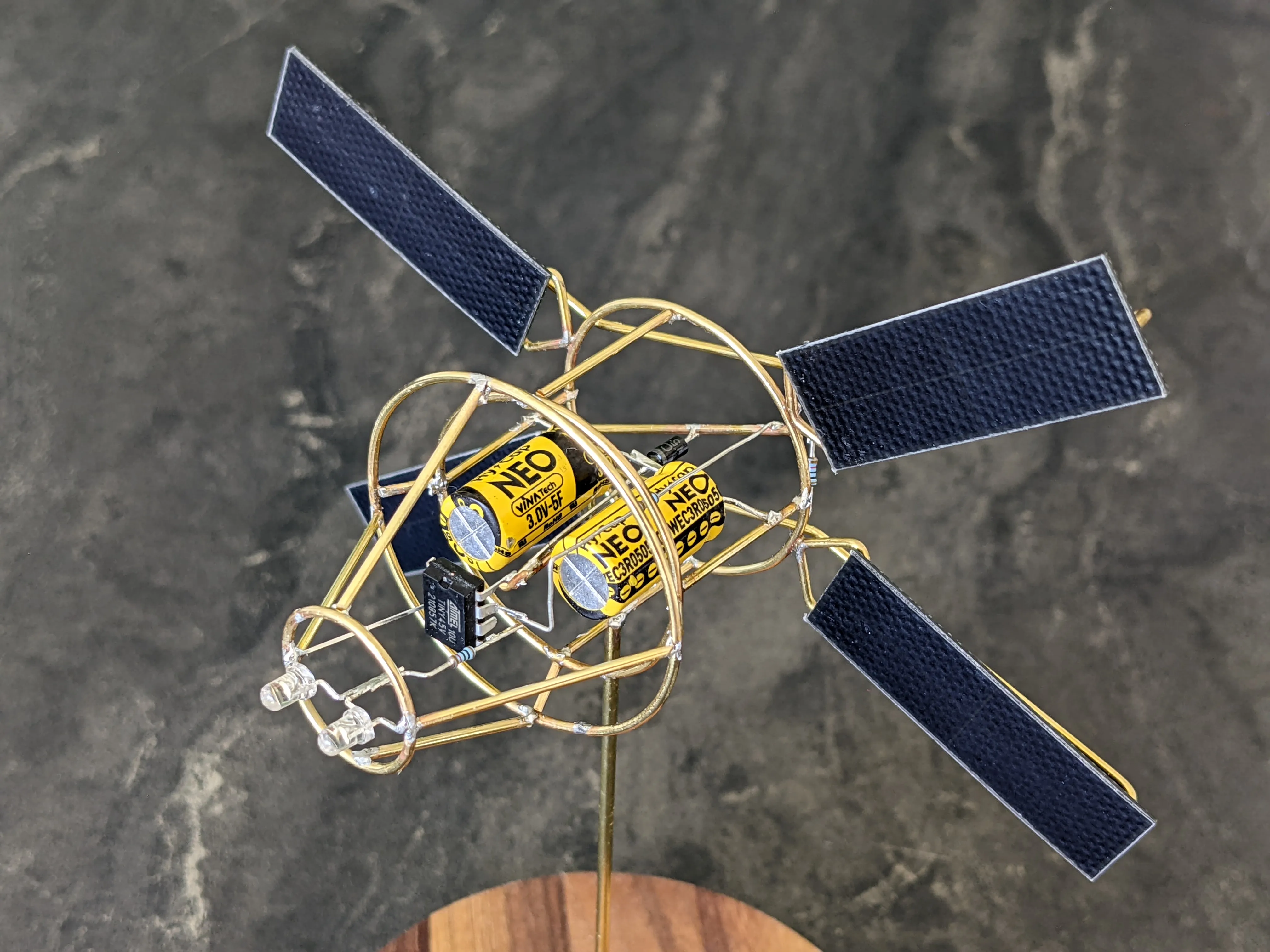
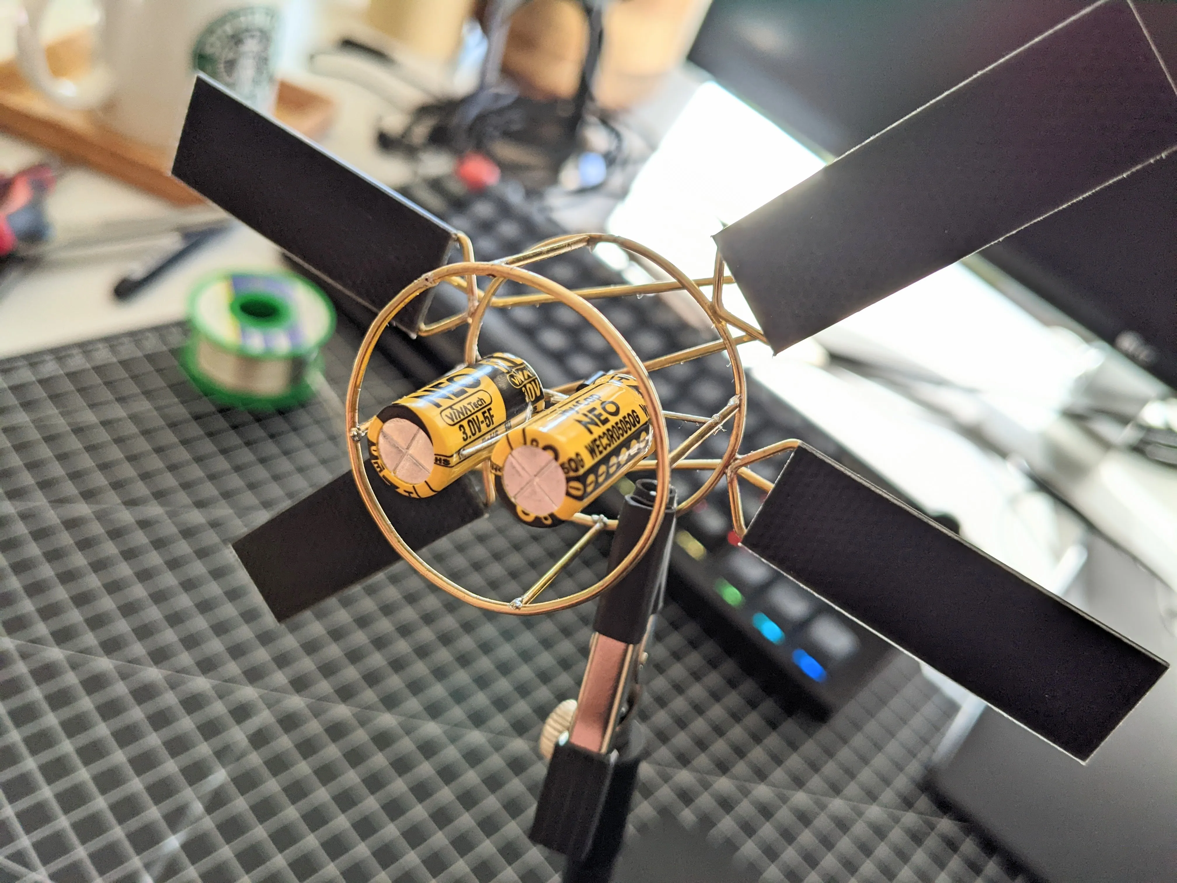
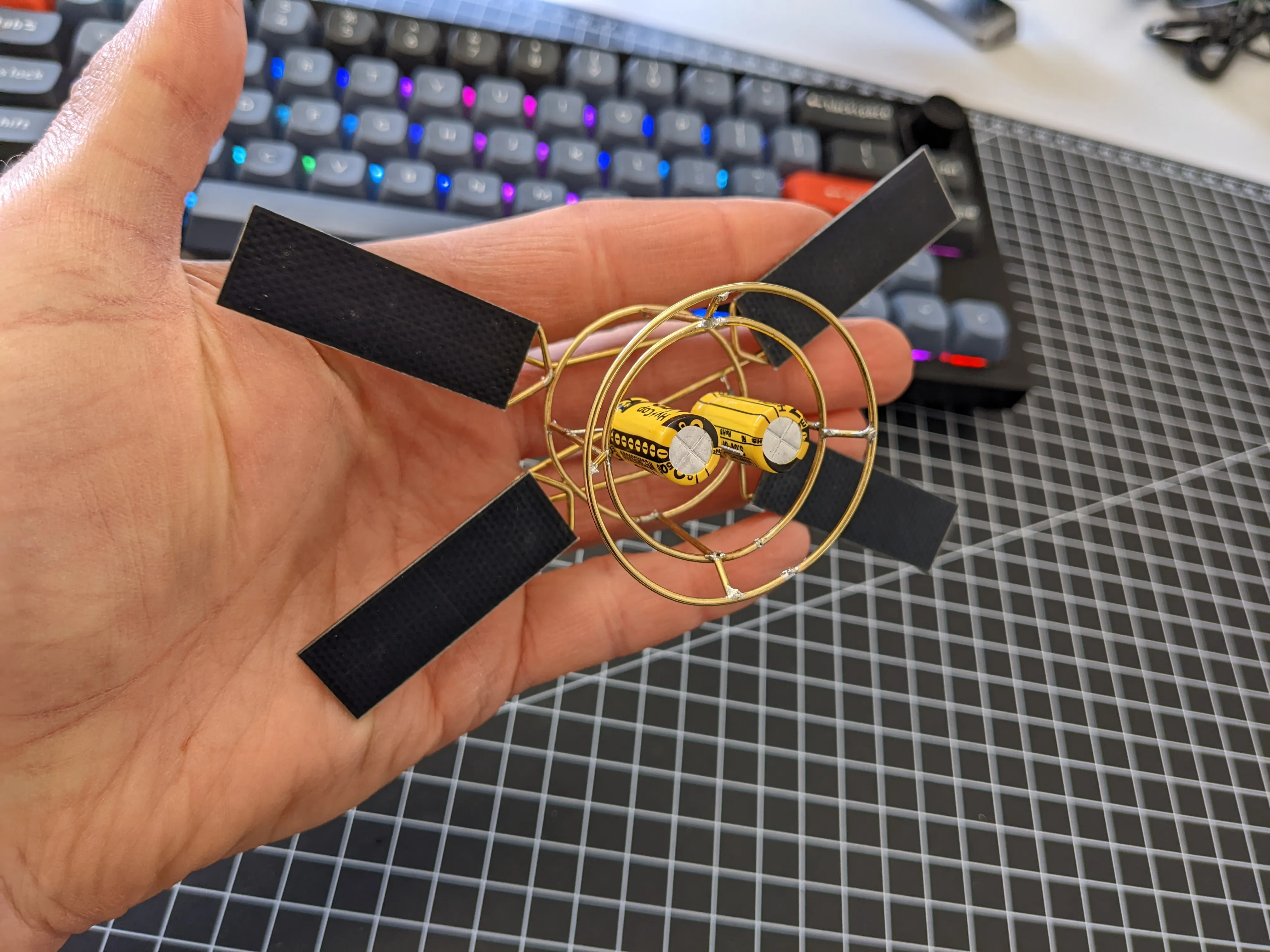
Here the capacitors are inserted in the model. At this stage the solar engine is complete and already running.
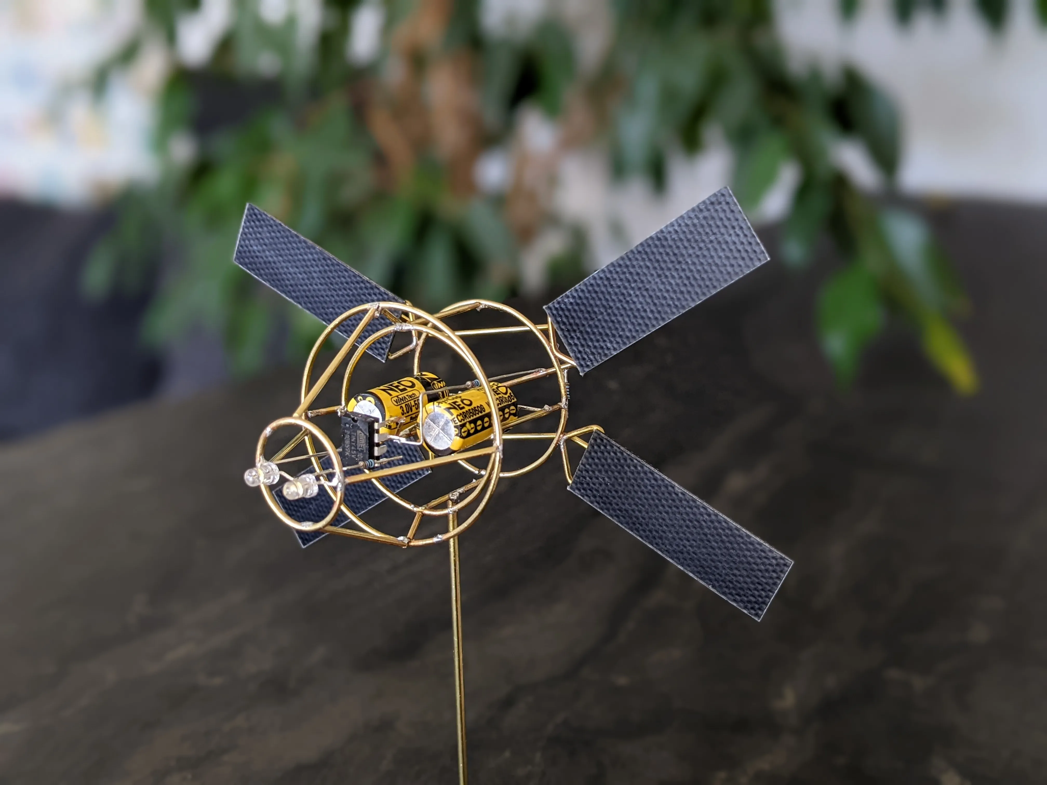
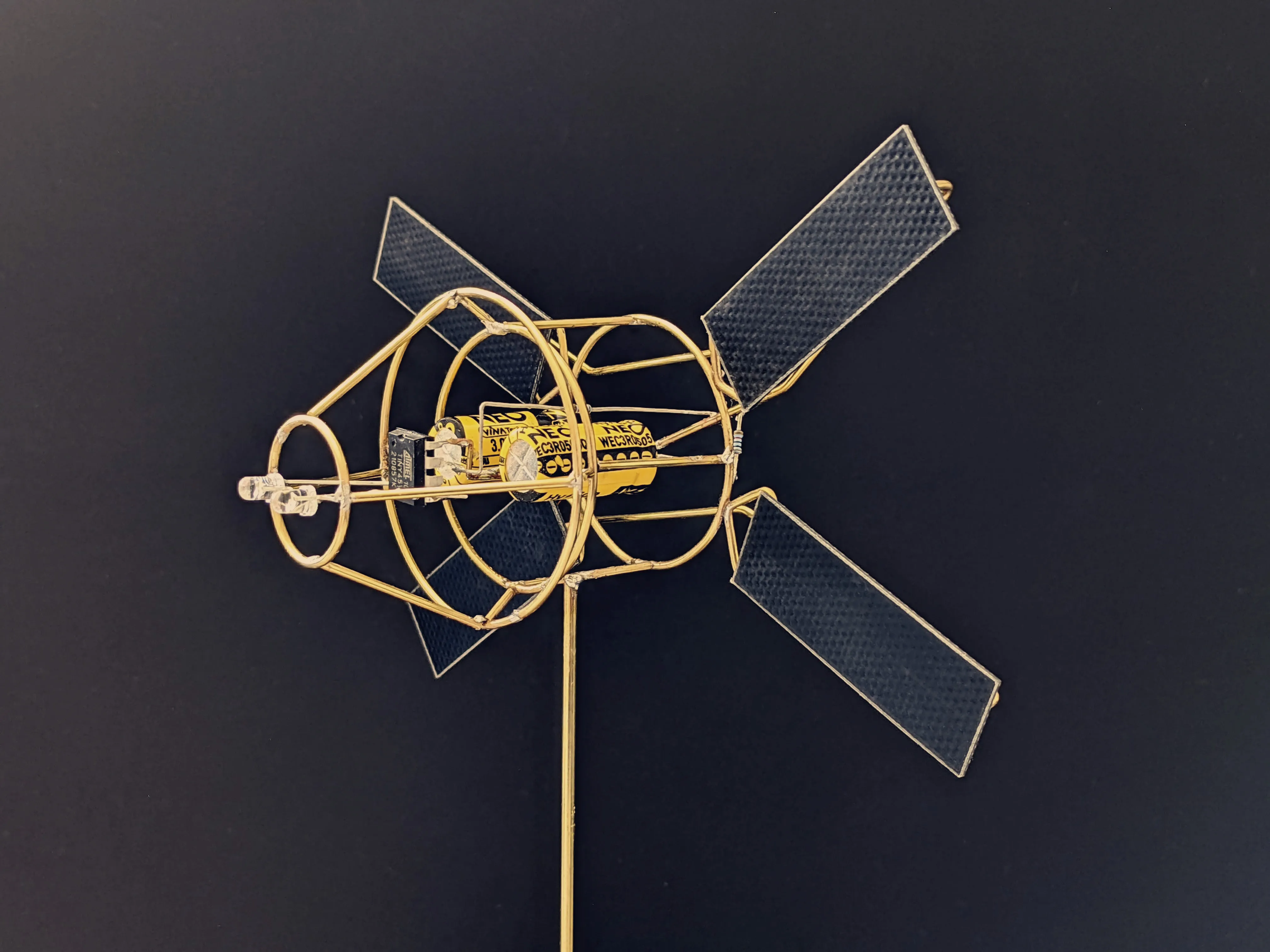
I continued ed my way forward, inserting the microcontroller and finished the brass structure. Very happy with the results (ᵔᵕᵔ)/

Gallery